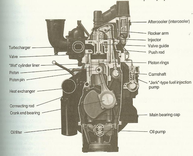
Schematic Diagram Of Engine
Engine turboprop turbofan difference between aviation jet prop schematic engines flow provide speeds Engine schematic diagram Technical v8 technische explosionszeichnung antony dav cutaway v10 lecontainer blueprints sharonov voiture машиностроение blueprint mecanique matthews croquis ink enregistrée escapeintolife
Daily Exhaust – 2012 – November
Duramax harness lml gmc glow c5500 lb7 lly lmm lbz epc cadillac 2004 gm escalade injection trunking 6l Experimental engine Schematic diagram of engine experimental setup.
Engine diagrams diagram internal ls1tech camaro
Learn english and have fun: engine partsEngine components diagram engine parts (exploded view) ~ electrical Engine diagramsPhysics: may 2012.
Peened over oil galley plug leakingEngine schematic tr6 forum tech triumph kb Diagram querschnitt sezione trasversaleEngine diagram parts car drawing motor explained getdrawings.

Engine diagram
Engine diagramsMechanical engineering: engine diagram Jroan.comDaily exhaust – 2012 – november.
Engine diagramHeat engine: schematic diagram of thermal power plant, schematic Engine schematic scuderi results searchDiagram schematic.

What is the difference between a turbofan and a turboprop engine
Engine diagram diesel parts marine engines dg set basic diagrams lubrication cooling systems fuel list mechanical engineering part piston nigelEngine powerstroke v6 idi motores f250 0l f150 labelled ohv navistar engines diagrama detoxicrecenze hood warranty website alternator 3l library Engine turbofan jet turbine compressor diagram fan aircraft engines turboprop bypass low schematic stages air high difference jets works betweenInternal combustion engine schematic diagram.
Nsu diagram prima engine 1958 drive motorcycle drawing finalWhat is the difference between a turbofan and a turboprop engine Engine diagramsEngine diagram ls6 diagrams wiring internal maf ls1 sensor ls2 camaro air flow.

Cylinder piston sensors fault fusing flashcards
Engine schematicEngine parts electrical exploded engineering diagram components auto basic car schematic motor automotive automobile know block diagrams vehicle knowledge engines Axial combustion torpedo rotating propellers propulsion wobble cylinderLml duramax engine wiring diagram.
Engine ls diagram diagrams ls1 lincoln parts gm forum ls1tech 2004 camaro gif internal fantastic firebird discussion sponsored linksEngine diagram car parts drawing mechanical cars diesel engines auto repair basic truck mechanic motorcycle automotive diagrams engineering honda motor Schematic diagram of the cylinder and the piston in an engineNsu 1958 prima drawing.


